11.3.3.3 build truth tables AND, OR, NOT, NAND, NOR, XOR Binary logic. Truth tables Binary logic At the most elementary level, an electronic device can only recognize the presence or absence of current or voltage. Either electricity is present or isn't. This is a switch - on or off, True or False, 1 or 0. With a computer's semiconductor, the voltage at the input and output terminals is measured and is either high or low; 1 or 0. Computers comprise billions of these switches and manipulating these sequences of Ons and Offs can change individual bits. Electronic logic gates can take one or more inputs and produce a single output. This output can become the input to another gate and a complicated cascaded sequence of logic gates can be implemented to from a circuit in, for example, the CPU. Logic gates and truth tables There are a number of different logic gates that are each designed to perform a different operation in terms of output. These are: NOT, AND, OR, XOR, NAND, and NOR gates.
source of gif: vivaxsolutions.com What is a truth table? A truth table is a table representing the output boolean values of a logical expression based on their entries. The table thus presents all the possible combinations of the input logical variables (generally 0 / FALSE and 1 / TRUE) and the result of the equation as output. NOT gate The NOT gate is represented by the symbol below and inverts the input. The small circle denotes an inverted input. Using 1s and 0s as input to a gate, its operation can be summarised in the form of a truth table.
AND gate
The boolean expression for AND is written: Q = A * B where * represents AND. The truth table reflects the fundamental property of the AND gate: the output of A AND B is 1 only if input A and input B are both 1.
OR gate
The boolean expression for OR is written: Q = A + B where + represents OR. The truth table reflects the fundamental property of the OR gate: the output of A OR B is 1 if input A or input B is 1. Creating logic circuits Multiple logic gates can be connected to produce an output based on multiple inputs
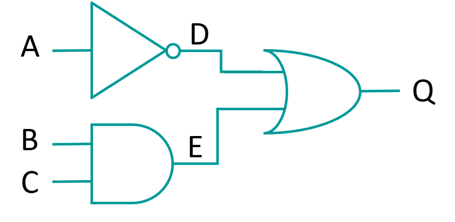
This circuit can be represented by Q = (NOT A) OR (B AND C) or Q = -A + (B * C) and shown using the truth table below:
XOR gate
The XOR (ex-or) gate stands for exclusive OR, meaning that the output will be true if one or other input is true, but not both. Compare this to the OR gate. Which outputs are true if either or both inputs are true?
The Boolean algebraic expression is written: Q = A ⊕ B where ⊕ the represents XOR, and is the equivalent of Q = (A * (-B)) + ((-A) * B). This gate similar to the OR gate but excludes the condition where A and B are both true. NAND gate The NAND gate is an combination of the AND and NOT gates, which inverts the output of the AND gate. Having a single type of NAND gate that can that can perform two separate functions can help to reduce development costs if a NAND gate is cheaper than separate AND and NOT gates.
The Boolean algebraic expression id is written NOR gate
The Boolean algebraic expression is written Source: AQA AS and A Level Computer Science Precedence of logical operations from highest to lowest priority
Questions: 1) Explain what is a boolean data type. 2) Build from memory the truth tables AND, OR, NOT, NAND, NOR, XOR. 3) What difference between AND and OR? 4) What difference between AND and NAND? 5) What difference between OR and XOR?
Exercises: Ex. 1 Ex. 2
Ex. 3 Tasks "Fill five the truth tables" Ex. 4
Ex. 5 Determine the result of the logic expressions with inputs. Ex. 6 Design logic gates circuits and build a truth table for each. Ex. 7 "Define result of truth tables" Exam questions: Draw a truth table for the following circuit (Marks: ):
| ||||||||||||||||||||||||||||||||||||||||||||||||||||||||||||||||||||||||||||||||||||||||||||||||||||||||||||||||||||||||||||||||||||||||||||||||||||||||||||||||||||||||||||||||||||||||||||||||||||||||||||||||||||||


 .
.
 . This gate only produces an output of true when both inputs are false.
| Input A | Input B | Input C | D = B OR C | E = A AND D | Q = NOT E |
|---|---|---|---|---|---|
| 1 | 1 | 1 | 1 | 1 | 0 |
| 1 | 1 | 0 | 1 | 1 | 0 |
| 1 | 0 | 1 | 1 | 1 | 0 |
| 1 | 0 | 0 | 0 | 0 | 1 |
| 0 | 1 | 1 | 1 | 0 | 1 |
| 0 | 1 | 0 | 1 | 0 | 1 |
| 0 | 0 | 1 | 1 | 0 | 1 |
| 0 | 0 | 0 | 0 | 0 | 1 |
| Всего комментариев: 0 | |